How to design an antenna with a PCB
Designing an Antenna using PCB
An antenna is an important component that is used to transmit and receive electromagnetic waves. It is used in various electronic devices such as radios, televisions, mobile phones, and many other devices that require wireless communication. In this article, we will discuss how to design an antenna using PCB.
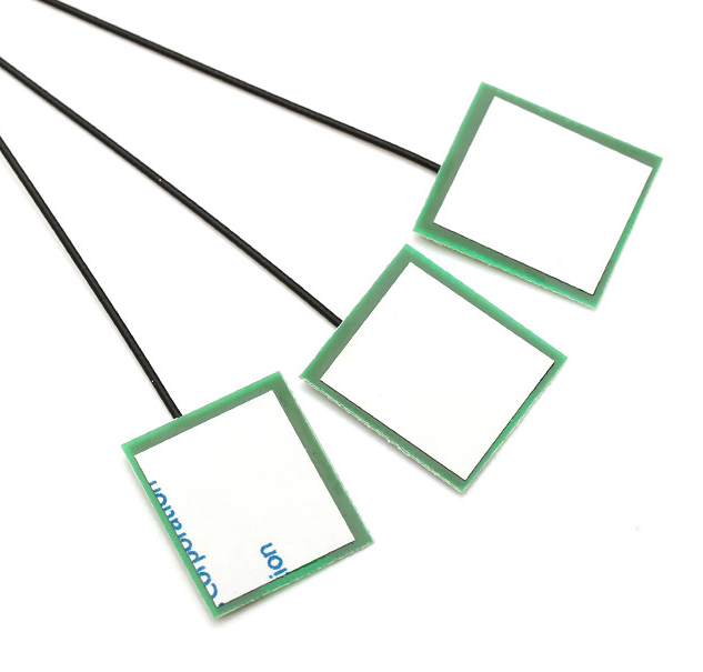
PCB, or Printed Circuit Board, is a type of board that is used to connect electronic components. PCBs are widely used in the manufacturing of various electronic devices due to their high precision, reliability, and cost-effectiveness. PCB can be used to design antennas since it allows for precise and accurate design of the antenna’s dimensions.
Designing an antenna using PCB requires some knowledge and skills in PCB design and antenna technology. Here are some steps that can be followed to design an antenna using PCB.
Step 1: Determine the frequency and type of antenna
The first step in designing an antenna using PCB is to determine the frequency range in which the antenna will operate. The frequency range will determine the type of antenna that will be suitable for the application. There are different types of antennas such as patch, dipole, monopole, and others. Each type of antenna has its own unique advantages and limitations. Therefore, it is important to choose the right type of antenna that will meet the requirements of the application.
Step 2: Determine the antenna dimensions
The next step in designing an antenna using PCB is to determine the dimensions of the antenna. The dimensions of the antenna will depend on the frequency of operation and the type of antenna being used. There are various software tools available that can be used to determine the dimensions of the antenna based on its frequency of operation.
Step 3: Create the RF path
Once the dimensions of the antenna have been determined, the next step is to create the RF path. The RF path is the path that the RF signal will follow from the antenna to the receiver or from the transmitter to the antenna. The RF path should be designed in such a way as to minimize the loss of the RF signal.
Step 4: Generate the PCB layout
The PCB layout is the final step in designing an antenna using PCB. The PCB layout should be designed with the antenna and the RF path in mind. The PCB layout should be optimized to minimize the loss of the RF signal and to maximize the performance of the antenna.
In conclusion, designing an antenna using PCB requires a combination of RF engineering and PCB design knowledge. It is important to follow the above steps to ensure that the antenna is designed to meet the requirements of the application. With the right knowledge and tools, designing an antenna using PCB can be a relatively simple and straightforward process.
